Designing products is a crucial aspect of many industries, and designers are often provided with high-performance computer systems to assist in their work. However, even with the best equipment available, designers may still encounter issues such as lagging and glitches in their CAD models. In this blog, we offer a unique perspective on CAD model design and provide solutions to common problems designers may encounter, which can help them optimize their workflow and improve their overall efficiency.
Let’s see what goes behind the Compact CAD Model and how it will help to increase the performance of your SOLIDWORKS.
Graphic Pipeline behind the CAD Model:
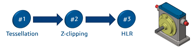
Computer Processes CAD Data into Tessellated Information and Following on, the Z-Clipping Algorithm will contribute to the HLR.
Finally, projection of CAD Model is Displayed in your Screens.
So, let’s have an overview of these terms and how they unknowingly they contribute to your CAD Design.
Tessellation is Subdividing Faces of Body in Triangles known as Facets.
Z-Clipping:
Algorithm where Computer decides which polygons to show from the respective view.
HLR (Hidden Lines Removal):
Hidden line removal (HLR) is the method of computing which edges are not hidden by the faces of parts for an entitled view and the display of parts in the projection of a model into a 2D plane.
Let’s see through an example:
.png)
.png)
So Just by Creating a simple Part model 192 Graphic Triangles are Generated. By Adding Simple Fillet, the Count of Graphic Triangle Increases by 20x.
.png)
.png)
Feature which are non-planar and helix cuts, threads create complex graphic triangles which will contribute to the slow performance of Large Assemblies.
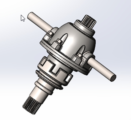
So, Assembly shown below has component over 7000 and Total Triangle Count is over 28 million.
Making Changes in such large assembly often frustrates the user as it would take time to load assembly, size being so large affect the simple action such as rotating and panning also.
Editing Such Assembly can be difficult sometime.
.png)
Performance in 3D equals Filled Triangles/Second:
.png)
Now let’s look at few solutions:
System Option Settings:
.png)
.png)
Defeature:
Tool will help you to remove details of the parts, assembly, multibody parts. Save the details to a new file where the details are replaced by dumb solids. Dumb solids are solids without feature definition or history.
You can share the new file without revealing the design details of the model. This Exercise will reduce the complex details as well as their facets.
![]()
.png)
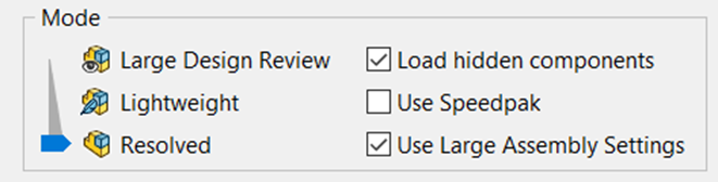
Large Assembly Modes:
SOLIDWORKS has provided the Large Assembly Modes to enhance the performance as the User can control the amount of tessellation data and other additional information should be loaded or not.
Large Design Review can be used when minute changes to be made as it opens Large Assemblies in a Snap.
Lightweight Mode leverages CAD Data and Graphical Data with Improved Performance.
Resolved Mode is Default mode in which the Model is loaded with Complete Information.
User can Leverage any of these mode or combination to faster and smoother working CAD Environment.
Large Assembly Setting Consists of Set Setting to Enhance performance such Display Options, Feature Tree Options, etc.
Conclusion
Merely investing in a high-spec computer system does not guarantee a seamless experience when using design software. It is crucial to adopt a strategic approach to design and have a well-planned design process in place to minimize delays caused by software lag and loading times. If you want to explore the concept of Design Intent or SOLIDWORKS in more depth, don't stop here! Contact Design Expert at Engineering Technique that can help you optimize your design workflow and enhance your overall efficiency.